
Thermal Buffers for AI Data Center Cooling
AI infrastructure needs more than cooling power; it needs verified thermal capacity across peaks, transitions, and recovery. Thermal-buffer modules and high-conductivity coolant additives engineered for AI workload thermal profiles — peak shaving, demand-charge offset, and recovery-window extension for high-density compute. See how the application fits into a complete PCM thermal energy storage system.
AI workloads stress cooling on three axes.
1. Density. Rack thermal loads at 50–120 kW are no longer outliers. Air-side cooling alone struggles to remove that heat at acceptable approach temperatures.
2. Volatility. Training jobs and inference traffic produce sharp thermal peaks that drive peak demand charges and short-cycle compressors.
3. Resilience. Cooling outages and chiller transitions create narrow recovery windows. Short interruptions can translate into expensive workload pauses.
Most facilities respond by oversizing — more chiller capacity, more redundancy. Thermal-buffer capacity is the alternative axis. A buffer absorbs the peaks, smooths the duty cycle, and extends recovery windows without committing to permanent additional cooling capacity.
Representative load profile
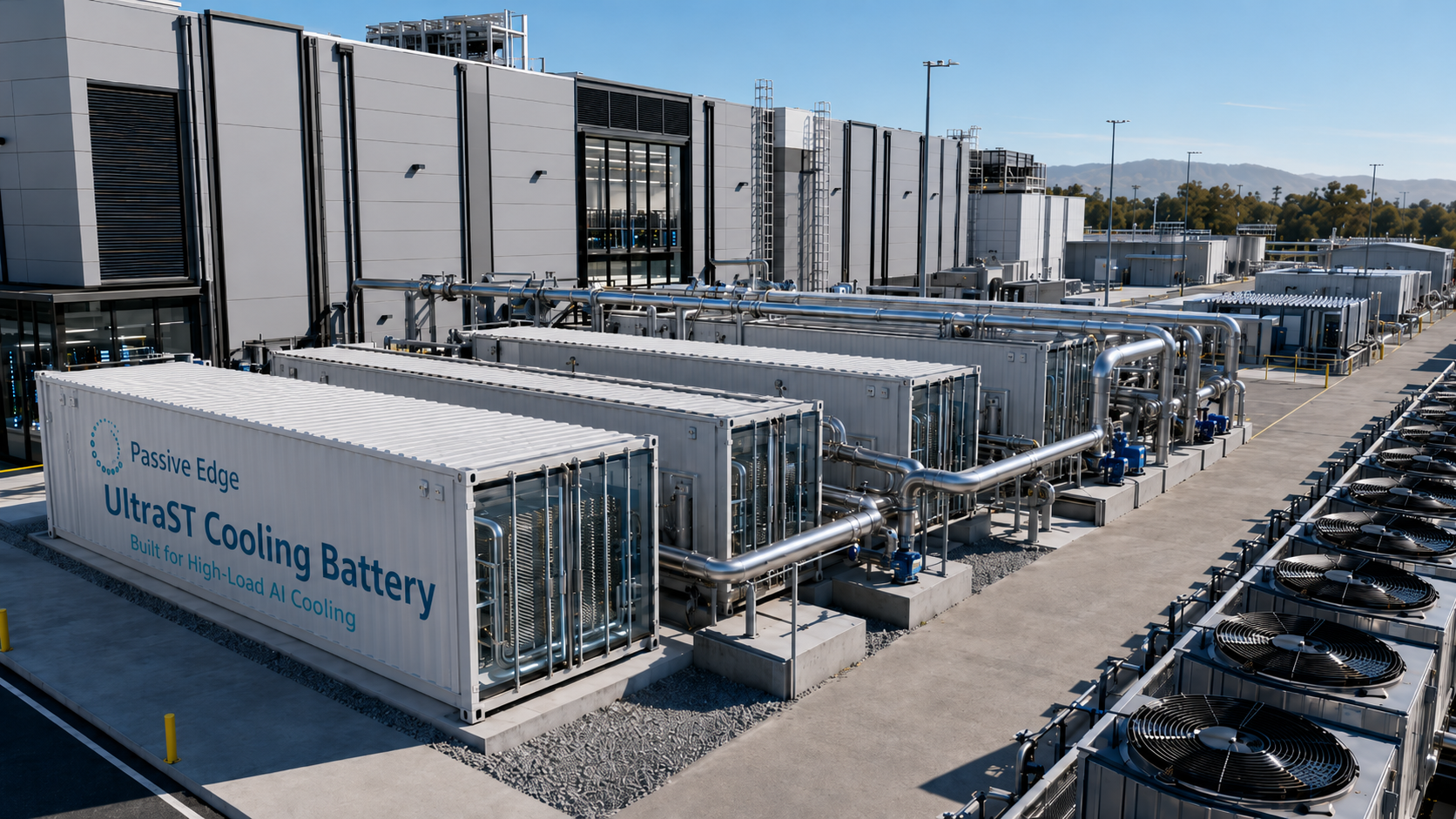
Container-scale thermal buffer, sited next to the load — absorbing peaks without permanent added chiller capacity.
From material to module.
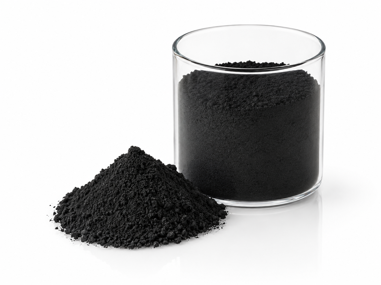
UltraST PCM + coolant additives
Specify Passive Edge materials into your own thermal subsystem. Use UltraST PCM as the storage medium and nano-coolant additives to lift conductivity of working fluid.
- PHASE POINTTunable, 20–60 °C window per project
- FORM FACTORPowder · Plates · Custom geometry
- DELIVERSMaterial + technical data package
- FIT FORTeams with internal thermal engineering capacity
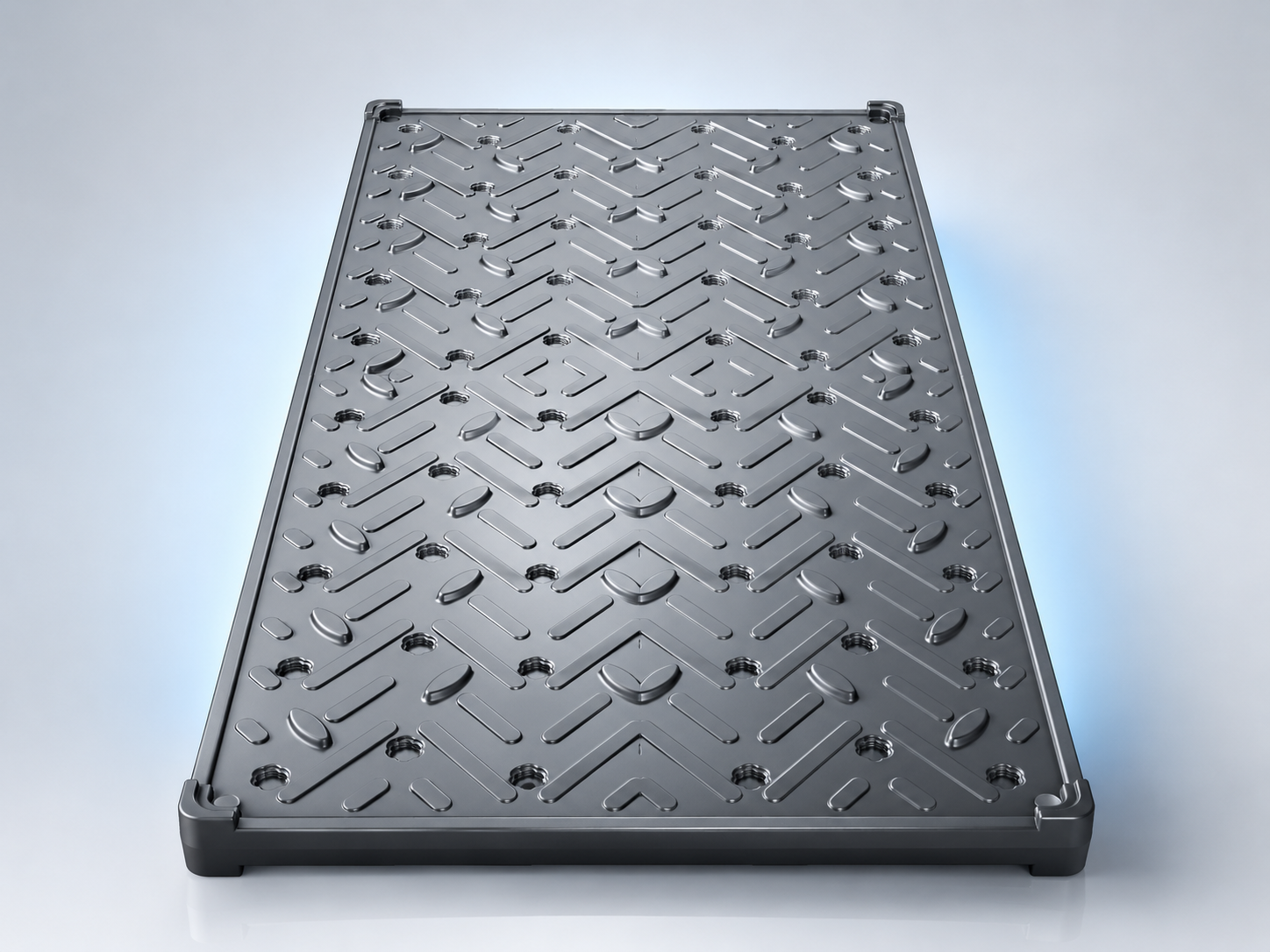
Thermal-buffer module
Pre-engineered modules built around UltraST cores, with integration interfaces matched to typical liquid-cooling and rear-door heat-exchanger topologies. Validated per project.
- FORM FACTORModular cores · Rack-adjacent or row-level
- CAPACITYSized per project — see the calculation tool
- DELIVERSModule + integration spec + pilot test plan
- FIT FOROperators wanting integration-ready system blocks
What we need before a fit assessment.
The more of the following you can share early, the faster we can return a useful response. None of these constitute a commitment from either side.
Have operating data? Explore sizing tools
From product selection to volume supply.
Project conditions submitted
You share load profile, topology, tariff, and target outcome. We return a written fit assessment within ~5 business days.
Material / system review
Joint review of which Passive Edge material or module is the best fit, with technical data package and integration spec attached.
Pilot test plan
Scoped pilot — typically rack- or row-level — with success criteria, instrumentation, and a defined validation window.
System-level validation
Pilot data review and engineering recommendation. Decisions about scaled deployment are made on validated evidence.
Build your internal case.
UltraST PCM data package
Phase-change temperature selection, latent heat capacity, conductivity, cycle stability data, encapsulation chemistry.
PCM thermal-buffer modules for AI data center cooling
Integration patterns for rear-door, direct-liquid, and immersion topologies. Sizing worksheets and pilot scaffolds.
GPU cooling thermal-storage sizing checklist
Inputs for load profiles, target buffer time, temperature band, recovery capacity, and validation windows.
S-Type PCM cooling cabin series manual
All published PE-DC-CS phase-change temperatures from 5-32 °C, calculated on one S-type cabin basis for early project sizing.
Share your application, temperature band, and load profile.
How it works
- Cooling source and load loop
- PCM buffer branch
- Heat exchange interface and PCM plates
Charge the PCM buffer while cooling is available.
Use stored cooling during a transition or rising heat load to provide a limited recovery buffer.
Recharge after cooling returns. Capacity for the next event depends on the actual charge state.
Structures and cycles illustrate the principle. Selection, capacity and performance depend on operating conditions and validation.