Flagship Application Layer 02 · System

AI Data Center Cooling.

Thermal-buffer modules and high-conductivity coolant additives engineered for AI workload thermal profiles — peak shaving, demand-charge offset, and recovery-window extension for high-density compute.

Material Layer
UltraST PCM · MOFPoly · Coolant additives
System Layer
Thermal-buffer modules · Thermal cores
Outcome direction
Peak shaving · Demand offset · Resilience
Delivery
Project review · Pilot test · Validation
Footage · data-center cooling environment
01Problem context
02Material / System option
03Project conditions
04Calculation tool
05Validation & review
01 / Problem context

AI workloads stress cooling on three axes.

1. Density. Rack thermal loads at 50–120 kW are no longer outliers. Air-side cooling alone struggles to remove that heat at acceptable approach temperatures.

2. Volatility. Training jobs and inference traffic produce sharp thermal peaks that drive peak demand charges and short-cycle compressors.

3. Resilience. Cooling outages and chiller transitions create narrow recovery windows. Short interruptions can translate into expensive workload pauses.

Most facilities respond by oversizing — more chiller capacity, more redundancy. Thermal-buffer capacity is the alternative axis. A buffer absorbs the peaks, smooths the duty cycle, and extends recovery windows without committing to permanent additional cooling capacity.

Representative load profile

Cooling demand vs. compressor duty — with and without thermal buffer
100% 75% 50% 25% PEAK SHAVED 00:00 12:00 24:00
Raw cooling demand Compressor duty with thermal buffer
Passive Edge UltraST Cooling Battery container modules installed alongside a high-density data center
Deployed · UltraST Cooling Battery

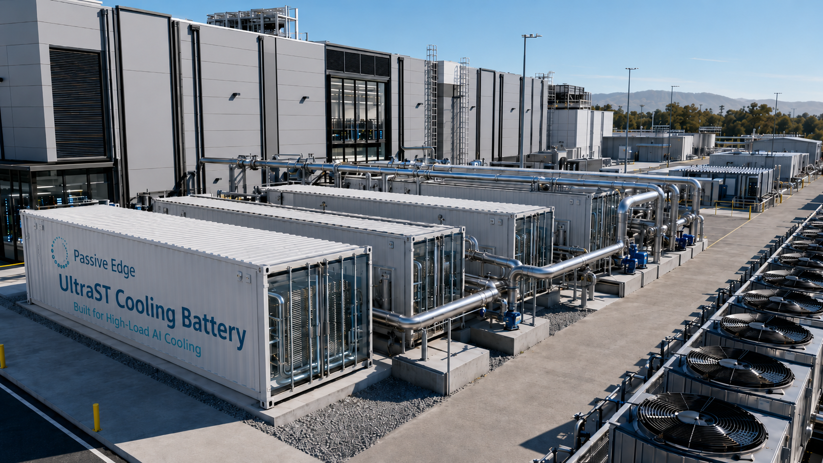
Container-scale thermal buffer, sited next to the load — absorbing peaks without permanent added chiller capacity.

02 / Material & System options

From material to module.

Two integration paths — depending on whether you want to specify your own thermal subsystem around our materials, or take a pre-engineered module from us.

UltraST high-conductivity all-solid PCM powder
— Material option

UltraST PCM + coolant additives

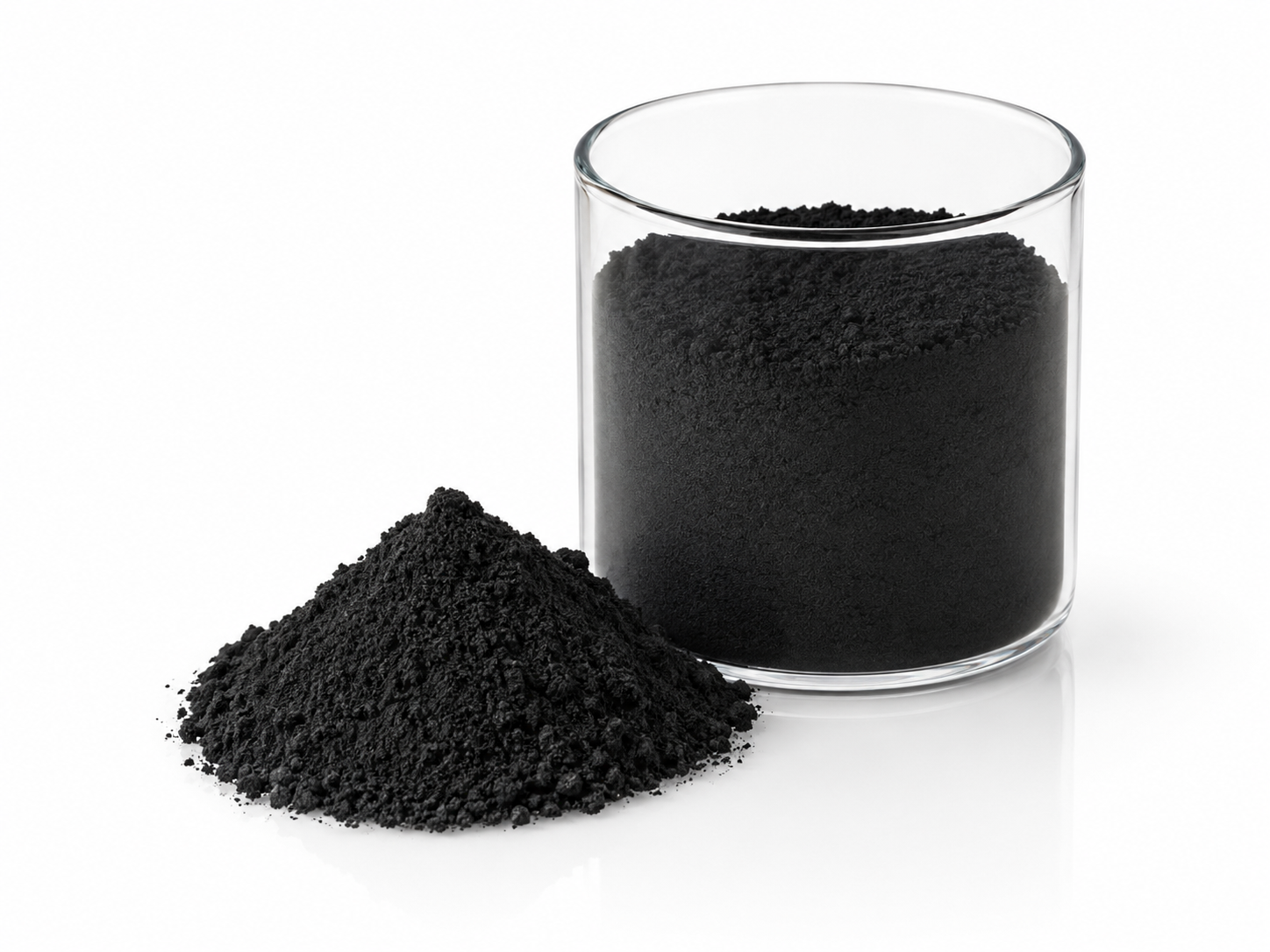
Specify Passive Edge materials into your own thermal subsystem. Use UltraST PCM as the storage medium and nano-coolant additives to lift conductivity of working fluid.

  • PHASE POINTTunable, 20–60 °C window per project
  • FORM FACTORPowder · Plates · Custom geometry
  • DELIVERSMaterial + technical data package
  • FIT FORTeams with internal thermal engineering capacity
Engineered UltraST PCM plate / thermal-buffer core
— Integration option

Thermal-buffer module

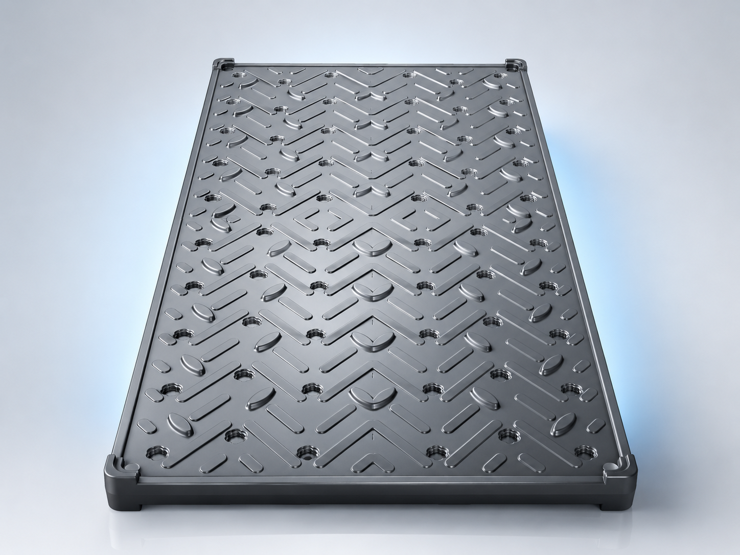
Pre-engineered modules built around UltraST cores, with integration interfaces matched to typical liquid-cooling and rear-door heat-exchanger topologies. Validated per project.

  • FORM FACTORModular cores · Rack-adjacent or row-level
  • CAPACITYSized per project — see the calculation tool
  • DELIVERSModule + integration spec + pilot test plan
  • FIT FOROperators wanting integration-ready system blocks
03 / Project conditions required

What we need before a fit assessment.

The more of the following you can share early, the faster we can return a useful response. None of these constitute a commitment from either side.

— Load profile
Rack count, per-rack thermal load (kW), training vs. inference mix, expected peak hours per day.
— Cooling topology
Air, rear-door, direct liquid, immersion. Supply / return temperature targets. Approach temperatures.
— Site & climate
Location, ambient envelope, available water, electrical infrastructure, footprint constraints.
— Tariff structure
Energy rate, demand charges, time-of-use windows, peak / off-peak deltas, capacity contracts.
— Target outcome
Peak shaving target, outage tolerance window, capacity headroom, decarbonization commitments.
— Timeline & stage
Greenfield design vs. retrofit. Decision stage. Existing thermal partners.
04 / Calculation tool

Size your AI cooling project on the Thermal Sizing platform.

The AI Thermal Sizing Tool models peak-shaving and demand offset against your load, topology and tariff. Outputs are directional — actual results depend on project conditions and validation.

05 / Validation & review path

How a project moves from conversation to deployment.

We work in clearly-bounded stages. No stage commits the next. Each stage produces a document you can use internally — even if you don't proceed with us.

— 01

Project conditions submitted

You share load profile, topology, tariff, and target outcome. We return a written fit assessment within ~5 business days.

— 02

Material / system review

Joint review of which Passive Edge material or module is the best fit, with technical data package and integration spec attached.

— 03

Pilot test plan

Scoped pilot — typically rack- or row-level — with success criteria, instrumentation, and a defined validation window.

— 04

System-level validation

Pilot data review and engineering recommendation. Decisions about scaled deployment are made on validated evidence.

Request System Review Submit project conditions
06 / Technical resources

Build your internal case.

Get in touch

Share your project conditions, load profile, and target outcome.

Our team will respond with a fit assessment, a relevant technical data package, and a proposed pilot test plan if there is a match.