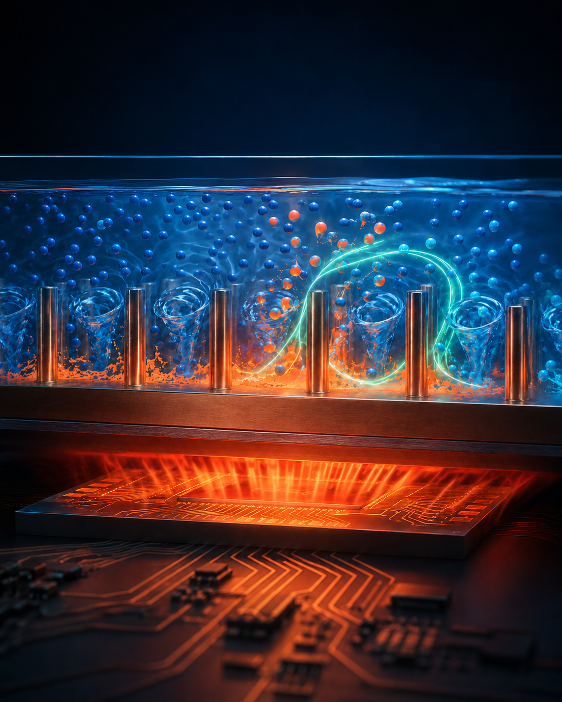
Nano PCM, PCM rubber, and UltraST ultra-high-conductivity shape-stabilized phase-change material sit at the heat source — chips, power-battery packs, motor drives — absorbing the thermal peak as latent heat and releasing it slowly. Zero added energy, no fans, no throttling cliff.
1. Transient peaks throttle performance. A chip or motor drive doesn’t run at steady power — it spikes. Fans and heat sinks respond on a slow time constant, so the junction hits its limit and the device down-clocks before the cooling catches up.
2. Confined devices have nowhere to dump heat. Phones, tablets, robot vacuums, and compact power tools have no room for active cooling. Heat builds at the source and the whole enclosure climbs.
3. Battery life pays the price. Lithium cells age fastest when they run hot and unevenly. Every degree above the comfortable band, and every thermal gradient across the pack, costs cycles.
A phase-change layer sitting at the heat source absorbs the burst as latent heat — holding temperature flat through the transition, then bleeding it back out slowly once the load drops. It buys the slow cooling path time to keep up.
EDGE Microna-PCM microcapsules (down to 200 nm) compounded into an elastomer. Leak-free through the phase transition, it conforms to uneven surfaces and fills the gap between die and enclosure.
PASSIVE EDGE® graphite-matrix shape-stabilized PCM — up to 20 W/(m·K) and rated for 20,000+ cycles. The graphite skeleton pulls heat in fast and spreads it evenly, so the latent capacity charges and discharges quickly.
A thin PCM pad over the SoC absorbs sustained-load bursts so the phone holds performance longer before it throttles.
Shape-stabilized PCM between cells evens out the pack’s temperature gradient and caps the peak during fast charge and high draw.
PCM rubber wrapped around the battery gives the cells zero-energy temperature control through dock-and-run cycles. Deployed in a Mijia-ecosystem unit.
Motor drives, fast chargers, and outdoor power gear that run in bursts — PCM blocks soak the duty-cycle peak so the electronics stay in band.
A robot vacuum’s lithium pack charges hard at the dock and discharges hard on the floor — a punishing thermal cycle in a sealed body with no room for active cooling.
Wrapping the cells in PCM rubber holds the pack inside its safe band and evens out the temperature across cells — with no added energy and no moving parts. The result was a markedly longer-lived battery and a longer service life for the machine.
The more of the following you can share early, the faster we can return a useful response. None of these constitute a commitment from either side.
You share power, duty cycle, temperature limits, and stack-up. We return a written fit assessment within ~5 business days.
Joint review of phase point, conductivity, and form factor — pad vs. shape-stabilized block — with predicted hold-band performance.
A sample part on a representative thermal load, instrumented for junction / cell temperature against your limit.
Cycle, reliability, and integration testing against measured data. Decisions to scale are made on evidence, not promises.
Phase-point options, latent capacity, conformability, microcapsule size distribution, dielectric and flammability characteristics, cycle stability.
Graphite-matrix conductivity curves, latent heat, 20,000-cycle stability data, machined-geometry options, and integration notes.
Cell-to-cell gradient control, fast-charge peak shaving, pack-level integration patterns, and a bench test scaffold.